 Bargain Chinese laser cutter/engravers typically come with funky proprietary controller hardware and software. While more-or-less functional, the software tends to be buggy, and limits future support availability and upgrade options.
This post details my experience converting my K40 Laser Cutter to use open source controller hardware.
I chose an AZSMZ Mini to use for the new controller. A variant of the Smoothieboard, the Mini is a compact unit whose built-in features make it very easy-to-use for this application.

I bought an AZSMZ Mini with stepper drivers and LCD display for $80 on eBay. As my stock control panel was stark and minimalist, I only had to rearrange some of its controls to make space for the new LCD display.
The first step was to build a support for the Mini and LCD board to mount beneath the control panel. I cut a bracket out of clear acrylic sheet and attached the controller and LCD to it with nylon standoffs. In front of this, I mounted a new control panel that I cut out of two-color plastic sign-making laminated sheet. Fortunately, a laser cutter is the perfect tool for doing this kind of work!


With the new control panel mounted in place, the next step was to hook up the controller board to the laser cutter power supply and motion control hardware.
Most others who have done similar upgrades have simply thrown out the old controller (in my case a Moshiboard) and painfully wired up the replacement directly to the existing power supply, stepper motors, and endstops, either directly splicing cables or using a Middleman board to aid in the process.
I, however, decided to take a different approach. Instead of tossing all
the old hardware entirely, I'd make my own adapter board that would allow me to
switch back and forth between the old and new. This would give me the
flexibility to use the best software for a particular job, as well as
options in case of an incompatibility or breakdown occurred in one specific software/hardware combination.

 I was surprised to find out how cheap custom circuit boards are to produce if one is willing to wait a month for shipping from the Far East.
I downloaded and learned a free design program called FreePCB and used it to layout my custom adapter board. It uses standard connectors and three CTS 206-125 dip switches to choose which controller to enable. The idea is to switch all dip switches to one direction (with the power off!) to select which controller board to use.
I had 10 boards manufactured at SeeedStudio for a total of 20 bucks.
Wiring up everything was super easy. The connectors on my adapter board line up in position and orientation with the ones on the Moshiboard, and are attached with short jumper cables. The only exception is one of the two FFC ribbon cable sockets (the one that connects to the Moshiboard), which I designed to be rotated 180-degrees around so that it could be connected with a very short FFC bent neatly back over itself into a U shape, as pictured below.
 | |
| Cabling Diagram |
The AZSMZ Mini has a built-in voltage regulator, so a single 24V power connection powers both the stepper motors and electronics. A single wire connects each of the X and Y endstops, and the stepper motors connect with simple 4-wire jumper cables. The fire line on cutter is active low, so a feature of the Mini simplifies its connection. The board comes with Mosfets that switch to ground for heater and fan connection, so I simply wired the fire line to the D8 bed heater terminal which is controlled by the PWM1 line.


With the hookup complete, the only thing needed to be done is configuration.
Smoothieboards support easy configuration via a config.txt file that is loaded at boot time from a MicroSD inserted in the main board.
Here is a copy of my configuration. I had to make adjustments from the defaults to calibrate my motor movement and direction, as well as lower the acceleration and fire PCM rates to get the behavior I wanted.

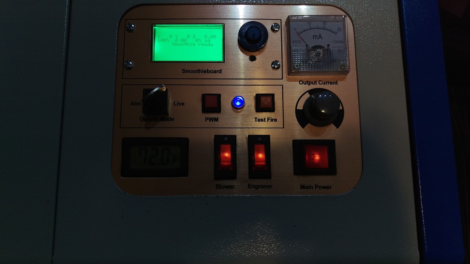
And here it is the result; all connected up and ready to go. I've made a few test cuts so far, and all is looking good!