Sunday, April 3, 2016

Hacking the K40 Laser Cutter

Bargain Chinese laser cutter/engravers typically come with funky proprietary controller hardware and software.  While more-or-less functional, the software tends to be buggy, and limits future support availability and upgrade options.

This post details my experience converting my K40 Laser Cutter to use open source controller hardware.

I chose an AZSMZ Mini to use for the new controller.  A variant of the Smoothieboard, the Mini is a compact unit whose built-in features make it very easy-to-use for this application.


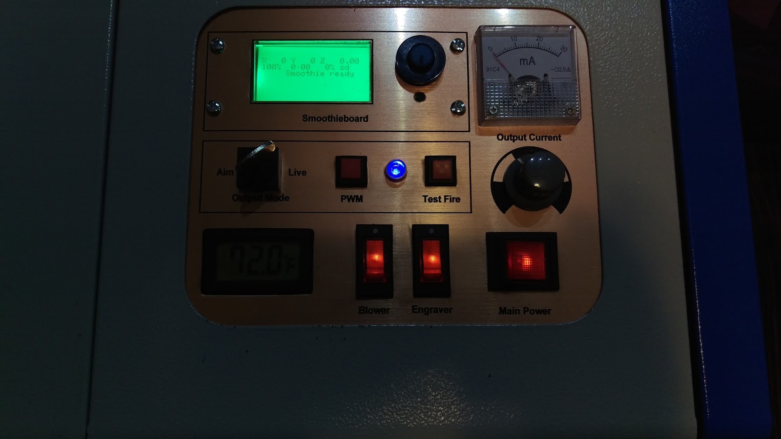
I bought an AZSMZ Mini with stepper drivers and LCD display for $80 on eBay.  As my stock control panel was stark and minimalist, I only had to rearrange some of its controls to make space for the new LCD display.

The first step was to build a support for the Mini and LCD board to mount beneath the control panel.  I cut a bracket out of clear acrylic sheet and attached the controller and LCD to it with nylon standoffs.  In front of this, I mounted a new control panel that I cut out of two-color plastic sign-making laminated sheet.  Fortunately, a laser cutter is the perfect tool for doing this kind of work!


With the new control panel mounted in place, the next step was to hook up the controller board to the laser cutter power supply and motion control hardware.

Most others who have done similar upgrades have simply thrown out the old controller (in my case a Moshiboard) and painfully wired up the replacement directly to the existing power supply, stepper motors, and endstops, either directly splicing cables or using a Middleman board to aid in the process.

I, however, decided to take a different approach.  Instead of tossing all the old hardware entirely, I'd make my own adapter board that would allow me to switch back and forth between the old and new.  This would give me the flexibility to use the best software for a particular job, as well as options in case of an incompatibility or breakdown occurred in one specific software/hardware combination.

While power supplies tend to come in many variations, Moshiboard controllers do not.  By designing an adapter board to replicate the Moshiboard connectors, I could simplify the wiring and reuse the existing cabling as well.  While some laser cutters have separate cables for endstops and the X stepper motor, mine combines them in a single flat flexible ribbon cable, so I made an adapter for this configuration.

I was surprised to find out how cheap custom circuit boards are to produce if one is willing to wait a month for shipping from the Far East.

I downloaded and learned a free design program called FreePCB and used it to layout my custom adapter board.  It uses standard connectors and three CTS 206-125 dip switches to choose which controller to enable.  The idea is to switch all dip switches to one direction (with the power off!) to select which controller board to use.

I had 10 boards manufactured at SeeedStudio for a total of 20 bucks.

Wiring up everything was super easy.  The connectors on my adapter board line up in position and orientation with the ones on the Moshiboard, and are attached with short jumper cables.  The only exception is one of the two FFC ribbon cable sockets (the one that connects to the Moshiboard), which I designed to be rotated 180-degrees around so that it could be connected with a very short FFC bent neatly back over itself into a U shape, as pictured below.

Cabling Diagram

The AZSMZ Mini has a built-in voltage regulator, so a single 24V power connection powers both the stepper motors and electronics.  A single wire connects each of the X and Y endstops, and the stepper motors connect with simple 4-wire jumper cables.  The fire line on cutter is active low, so a feature of the Mini simplifies its connection.  The board comes with Mosfets that switch to ground for heater and fan connection, so I simply wired the fire line to the D8 bed heater terminal which is controlled by the PWM1 line.


With the hookup complete, the only thing needed to be done is configuration.

Smoothieboards support easy configuration via a config.txt file that is loaded at boot time from a MicroSD inserted in the main board.

Here is a copy of my configuration.  I had to make adjustments from the defaults to calibrate my motor movement and direction, as well as lower the acceleration and fire PCM rates to get the behavior I wanted.


And here it is the result; all connected up and ready to go.  I've made a few test cuts so far, and all is looking good!

Sunday, January 17, 2016

DIY Filament Factory

Winder box with Filastruder on top
As a frequent 3D printer user, I sometimes go through a spool of filament... well... faster than a redneck goes through second cousins at a family reunion.  While the price of filament has dropped significantly in recent years, raw plastic pellets can still be bought for less than one-third the cost.

To take advantage of this, a number of solutions exist for making one's own filament, including the Filastruder, a kit I received a prior Christmas.   Cleverly designed from largely ordinary hardware, the device extrudes filament by squeezing plastic pellets with an auger bit down a heated length pipe and out a small nozzle.

I'd always had mixed results using the Filastruder, however, as reliable use requires suspending it in the air over a large open space.  Otherwise, that the fragile molten filament can catch on furniture or itself, causing the resulting product to kink, snag, and be otherwise unusable.  This made it a real hassle to use, especially since even a slight air movement from opening a door or walking by could disturb the filament. With little Monkeys about, this was not a realistically achievable scenario.

For a more convenient system, I decided to try making a simple filament winder that could take up the filament as it is produced, keeping it neat and consistent.  While a commercial winder kit exists, I could justify neither the cost nor large wall hanging space it requires when set-up.  Instead, I chose to make one of my own design; one that didn't require the same finicky electronics.  It would also be a challenge which added to the fun.  Lastly, I came up with the idea of building it into a handy portable case that could house both itself and the Filastruder, keeping them free of dust and out of the way when not in use.

I created a frame for a simple plywood box, roughly 20 inches square and 6 inches thick.  I stained it and added a leather handle and some brass hardware, fancying that this gave it the appearance of some bizarre 19th century science experiment or instrument of medical quackery.


The toughest part of the design was finding a way to sense slack in the filament without disturbing the path of the filament itself.  As the new filament comes out molten, I found that even the lightest micro-switch I could find would transmit too much force back up the filament and cause a kink near the nozzle opening.

Other winders use linear sensors, but they require a microprocessor and more complexity, which I hoped to avoid. After trying mercury switches and considering magnetic reed switches and other sensors,

I settled on a lightweight 3D-printed "see-saw" rocker that I weighted down slightly on one side.  The filament moves in a loop down the left side of the box, across the bottom, and up the right side.  When the filament develops too much slack, the bottom of the loop pushes down on a curved acetate surface glued to one side of the rocker. This lifts up the other side, raising a shutter that exposes a CDS-cell light detector to a single LED light source.

The cell is connected to a solid state relay that drives a small gear motor and the take-up spool.  I also added a cheap $5 PWM motor speed control board to allow fine-tuning of the motor speed.

To evenly guide the filament onto the spool, the filament passes through a short length of tubing mounted onto a hinge.  As the hinge moves, the filament comes out at a different place on the reel, keeping it from bunching up in one place.

The hinge, in turn, is linked to a carriage, that moves up and down along a worm gear (threaded rod) driven by a second gear motor.  Two momentary limit switches keep the carriage from moving too far in either direction. They simply switch on and off a DPDT latching relay, wired in a way (one on, one off) so that the motor reverses direction when either switch is hit.


After my initial tests, I also added a small, spring loaded clamp to keep the filament under tension.  This was needed to keep the filament tight on the reel.

Here is the completed winder case.  When in storage, the Filastruder fits neatly inside with hanging space for an empty or full filament spool.

When I'm ready use it, I simply set the extruder on top of the case and pass the new filament down through a hole in the top and loop it round to the winder inside.

I was surprised how well it worked right off the bat.  The rocker assembly tends to stay right on the edge between on and off, moving ever so slightly to periodically activate the take-up motor.  The movements are so small that the filament path moves very little, leading to the most consistent filament than I've ever made before.

I've already successfully used it to create two one-pound (half-size) spools. I'll still probably buy some filament, particularly for special colors and specialty plastics.  When I need simple black or white filament, however (the colors I use the most), from now on I'll probably just make my own.


Tuesday, December 22, 2015

Backyard Climbing Wall

What Little Monkey doesn't want to climb?

When ours have more energy than can be safely confined within four walls, we always find it essential to have a selection of outdoor distractions.  After two trips to a local climbing gym, we decided that our own climbing wall would make a great new addition.

Fortunately, we had previously built a large play structure that was ensconced in a cushy layer of rubber bark.  One of its walls would be perfect for erecting a modest 10-foot wall for climbing and bouldering.


The first step was to assemble the materials.  Since the wall would be outside, this meant choosing materials that could weather the... well...weather.

I bought some pressure treated 2x4 beams from which to construct a frame, and two sheets of 3/4 pressure treated plywood to be used for the wall face.  The sheets needed to be prepped with deck wash prior to covering.  Fortunately, my helpers thought this was a fun task to do.
To anchor the holds, I created a template in scrap wood, and the Little Monkeys and I used it to mark out and drill mounting holes in the plywood, laying them out in a modified 8-inch grid pattern with every other row staggered sideways by half a column width.
To give it a nice grippy rock-like appearance, I bought a gallon of DeckOver textured deck coating in a dark gray color.  Since this stuff is normally used to repair damaged decks, I figured it would be perfect to both protect the wall and give it the durable surface for climbing.  The stuff is really neat and unbelievably thick.  It fills in cracks and crevices (enhancing the "rock" feel), and goes on more like drywall compound than ordinary paint.

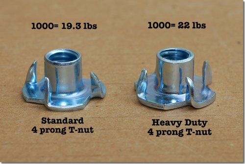
200 Heavy Duty 4 Prong Zinc Plated 3/8" T-nuts (For 8' x 8' wall)Into the holes, we hammered in stainless steel T-nuts from the backside of the wall.  These would be used later to fasten holds to the wall with 2-inch stainless hex bolts.
Genuine climbing holds are easy to find on eBay.  I found a colorful assortment of 40 beginner-level "bolt-on" holds that fit the bill for about $70.  After mounting them to the wall, we were ready for some test climbing.
The Little Monkeys took to the wall right away... maybe a tad too quickly...


Part of the reason for making the wall was to give the Little Monkeys a place to get used to their climbing harnesses and practice repelling down after a climb.  So to make a top rope V anchor, I used 3/8" chain, bolts, wall hangars and locking carabiners, all in stainless steel.  


With that in place, they had their choice of bouldering and top rope climbing, and the wall was done.


Sunday, November 22, 2015

Steamer Trunk Coffee Table (with Stealth Cutting Laser)

What beats a plain coffee table? A coffee table made from a steamer trunk. What beats coffee table made from a steamer trunk? A coffee table made from a steamer trunk that hides a liquid-cooled cutting laser inside, of course.

In brainstorming ideas for a permanent laser cutter home, I got stuck on the idea of building it into a table.
Steamer trunk with a hidden surprise
I looked online for ideas and really liked the look and hidden storage of "steamer trunk" coffee tables. The laser cutter was already quite large, however, so I wanted the trunk that didn't have a lot of extra wasted space. None of the existing tables I found came even remotely close, though, so my only option (fortunately) was to construct one from scratch.

Cutting angle iron
Most steamer trunk coffee tables I found were built to resemble a classic steamer trunk resting on some sort of stand, perhaps with shelving below for magazines and such.

I decided to make mine out of plywood and steel and give it a distressed industrial look. I bought about 50 pounds of angle iron from Big Orange to make the frame. To cut the steel to length and miter the ends, I used a portable bandsaw from Harbor Freight that I'd mounted on a small stand.

Welding
Sadly, my existing welding skills were pretty sucky, so the next step would be tricky. The project required a lot of welding, so I'd have to step my game up to get it done. Fortunately, it also offered ample opportunity to practice. At the beginning, my welds were a brittle, lumpy mess. After a couple of false starts and more redos than I would have liked, I finally figured out that by carefully cleaning the metal beforehand and keeping the wand close to the surface, I could get a reasonably clean bead.

Full welded frame
Welded base
With that knowledge in hand, I welded together the table frame, creating both the trunk and a base unit that would hold a rack for sheet materials and the water supply.

Painting
Adding straps
After the frame was fully assembled, I sprayed it with rust-colored red primer followed by an oil rubbed bronze paint. When it dried, I lightly sanded the edges to give it a faux weathered appearance.

To complete a steamer trunk look, the frame included steel simulated "leather" straps, which I sprayed a contrasting copper color.

Caster wheels
To give the table mobility, I found some nice cast iron caster wheels on Amazon, and painted them the same copper color as the straps.

I didn't want the hard wheels to scratch the floor of my Man Cave, however, so I printed polyurethane rubber treads for them on my 3D printer using Ninjaflex flexible filament.

Corner hardware
From the Rocker woodworking store, I got some very nice streamer trunk hardware to make everything truly authentic, including corners, latches, and hinges.

They really sell the illusion. A light dusting in copper paint helped them blend in.

Staining wood
Distressing plywood
For side panels, I used hardwood plywood, and recuited Little Monkey and Littler Monkey to distress them before staining. Their eyes lit up when I gave them hammers and told them they could let loose with them.

I attached the paneling to the frame with button head cap screws to mimic the look of rivets. The hinges, handle, and corner hardware were fastened the same way. With the addition of some wire shelving on the bottom, and some access holes in the bottom, the table was complete, ready for its new occupant.

Hinging top to base

Installing laser cutter
I modified the laser cutter internally to route exhaust fumes to the bottom of the unit instead of the back, and also added some switched outlets so the fan and water pump could be enabled from the main control panel.

I inserted the laser cutter carefully, routing each water hose and power line through its corresponding hole in the trunk button. It was an incredibly close fit, with less than 1/4" clearance all around. In fact, I had to order a special right angle power plug to replace the one that came with the unit, and even had to shave that to make it fit.

Cutting name plate
Finished nameplate
As a final touch, I used the laser cutter itself engrave a nameplate for its home.

Completed table with Engraver
With the trunk top open, the laser is ready for action in all its blazing glory.

Assembled table
But with the top closed afterwards, all one sees is a handsome piece of furniture with nobody the wiser.