Monday, December 2, 2024

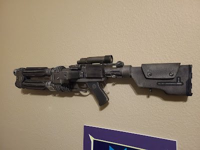
E22 Shoretrooper Blaster (from Star Wars: Rogue One)

I don't generally get to spend a whole lot of time making props.  I've enjoyed a few I've done, but don't have a lot of storage or wall space to store or display many new ones.

An opportunity started two years ago, however, when our youngest had an ambitious plan to build -- with help over the course of a year -- a Star Wars-themed Halloween costume beginning with an E-22 Shoretrooper Blaster from Rogue One.


We started with some soldering lessons to put together a sound effects box to play recorded "pew-pew" sounds with every trigger press.  As a bonus, the included battery box matched the size and appearance of a box on the left-hand side of the E-22.


The trigger and handgrip were fashioned from scratch respectively from aluminum and wood and mounted to a PVC pipe and wood frame that would represent the base of the blaster.  An internal spring and microswitch completed the working trigger mechanism.


With a coating in black spray paint, it was already starting to take shape.


To refine the shape of the double barrels, sheets of EVA foam were wrapped around and attached with hot melt glue to add thickness and shape.


Additional foam was added to cover the wood stock and barrel spacer pieces, and successive layers were built-up to add more thickness, ridging, and other details.

Additional details were added with sheet aluminum pieces, brass brads, and screws.


After this point, the project sat fallow for over a year and a half as its instigator found other interests and other priorities took precedence.  Momentum began once again, however, after our oldest expressed interest in helping complete the E-22.

So more pieces were added one-by-one to build the scope, light, magazine, and other pieces from more PVC pipe, wood, aluminum, foam, screws, and random scrap parts I found lying around that happened to resemble pieces in reference photos from the movie.


Some curved laser cut pieces added the critical cooling fins to the barrels.

After a base of black spray paint, it was starting to look like a "real" thing.


After adding salvaged strip magnets from a fiberglass screen door that had the right shape for barrel ridges, silver paint was added to "metal" parts to give a more realistic appearance.


To finish it off, some more black paint was added with a small brush for grime and weathering as well as hand-painted details.


The E-22 was finally finished.  Pretty good, I think for a first try at something quite like this.

Monday, November 4, 2024

Upgrading a k40 Laser Cutter Bed

At about $400, a k40 Laser Cutter is a wonderful low-cost entry into the world of laser cutting and engraving, and also a great platform for hacking and upgrading.

The biggest limitation of a k40, however, is the size of the engrave-able area, which is limited to just 8x12 inches.  This suffices for many projects, but often is a source of frustration when trying to create something larger, or even just for efficiently using materials that come in 12x12 sheets.

While enlarging the k40 bed is a common desire, the most popular upgrade along these lines is a full 12x24 rebuild of the laser gantry, gutting both the electronics and gantry parts of the case, building a custom gantry in its place, and relocating the electronics to an external case.

12 x 12 cutting / engraving area

For myself, I wanted to try something more restrained; a 12x12 cutting area retrofit to fit entirely into the existing cutting bay.  I found inspiration when I came across a budget laser engraver kit for just $99 on Amazon.


When assembled it would be tight, but seemed like it would fit in the existing k40 bay with a little encouragement.  My plan was to laser cut some adapter pieces to hold the y-axis mirror and laser head, then adapt the gantry, gut the k40, and swap in the new for the old.


Unfortunately, after gutting the k40 internals, I found out I had mis-measured.  The back of the k40 has reduced vertical clearance due to the laser tube compartment hanging down from above, and the x-axis from the diode laser could never fit underneath it to allow the full 12" of y-axis movement I wanted.


The only way I could get it to fit was to reuse the original k40 x-axis, mounting it in place of the one from the diode laser with some acrylic adapter plates.  

My laser cutter was now inoperable, so I hand fabricated various pieces from acrylic and plate metal to hold everything together well enough to make the laser cutter operational again.  This included a new mount for mirror 2, attaching it to the end of the x-axis...


and a holder for the laser head, adjusted to tuck underneath the laser tube compartment.  These would get rebuilt later once everything was up and running, but in this early version, it was finally fully functional after a fair amount of tweaking, and had a full 12x12 cutting and engraving area I wanted.


Movable cutting bed (z-axis)

After getting the laser operating again with the enlarged cutting area, my attention turned to the cutting bed.  Since I sometimes cut 1" foam sheets such as for camera case inserts, I wanted a bed that could move up and down to adjust for different material thicknesses, all without affecting levelness.

My idea was to create a frame for the bed that would be supported on all 4 corners by captured nuts and threaded machine screw legs that turned in sync by gears driven by a circular toothed belt.


A small gear-motor would drive the gears in either direction in response to a DPDT toggle switch to move the bed up or down.


A spring-loaded idle wheel maintained tension on the belt, and could be released it I needed to turn one of the screw legs manually to level the bed.


Here is the completed bed (upside-down), built from scrap aluminum fence post material and the above-mentioned gears, belt, and motor.


And here is the completed bed right-side-up during motion testing.


Tuesday, October 1, 2024

Catching up on Small Projects - Oculus/Meta Quest

I haven't written in a long time, and thought I'd do some quick posts of small projects I've worked on.  The first is for a number of small projects I've completed for the Oculus (now Meta) Quest VR headset.  

Like many people, my family got our first Quest 2 during the pandemic as a way to "get out" more during lockdown.  To this day, I still use my Quest 3 fairly often, sometimes playing for a whole afternoon on the weekend when I'm hooked on a particular new game.  During such long play sessions, opportunities to improve the experience presented themselves, leading to a few quick projects.

3D-Printed Back Weight

The first quick project was a way to help balance out the headset to make it more comfortable.  While there are a number of great after-market head straps to adjust pressure points and fit around the head, the headset still tends to be front-heavy, which I found would give me a neck ache after hours of continuous play.  


While some people use external battery packs strapped to the back of the headstrap, I like to play plugged in, and created a curved, hollow 3d-printed back-weight which I filled with copper slugs.

Staying Charged when Playing

When playing plugged-in, the choice of cable and charger are critically important.  In order to play continuously, the Quest must communicate with a smart-charger and coax it into a higher-voltage fast charging mode instead of the USB default of 5 volts.  Otherwise, the battery will drain faster than it can charge and will die after a few hours.  To do this, one must have a USB-C charger capable of fast-charging, and exclusively use USB-C cables and connectors along the way.  This is because USB-C connectors and fast-charge cables have extra wires used for voltage negotiation, while old-style USB connectors do not.

Since a lot of chargers and cables lie when they claim to support fast-charging, spend an extra $10 for an inline USB-C Inline Voltage Meter to verify the charging current and voltage (hint: get one with the male connector on a pigtail, as ones sticking directly out of the device easily break off).  Here, we see a Quest 3 fast-charging at 12 volts instead of only five.


Also invest in short right-angle usb-c extension cable which you can attach to your head strap and leave permanently attached to the headset.  This will save wear and tear on the delicate USB-C connector, and act as safety disconnect mechanism when accidentally stepping on, or otherwise snagging the cable.

USB-C Rotary Charging Cable Connector

An unfortunate side effect of playing while plugged in -- especially with shooting or fighting games -- is getting the cable twisted all up.  While I've tried a number of magnetic swivel connectors, these tend to come apart too easily from the weight of the hanging cable, and none have supported the extra wires needed for fast charging.

To solve this, I came across slip-ring connectors, electrical components which can maintain an electrical connection to a rotating device.  They use sliding brushes to keep connections intact across a built-in rotating shaft.  This probably makes them too electrically noisy for data, but seemed ideal for power transfer.  I spliced one into a short USB-C extension cable, being sure to connect power, ground, SBU, and CC lines, creating a handy adapter that automatically unwinds any twists in the line while I play.


Golf Club Controller Extension

Recently, I've found myself taking a liking to a number of VR sports games for sports I've shown relatively little interest pursuing in real life.  Perhaps that's the point of VR: taking in experiences that are too expensive, intimidating, dangerous, or simply too much of a hassle to partake in otherwise.

One such game is Golf 5 for Quest, which I've found to be realistic and fun.  The one thing I wanted, however, was to have an accessory that extended the controller to give a place for my back hand for a more natural grip and swing.  There are a lot of existing "golf" controller accessories for Quest, but they generally fall into two categories:

  • A fairly long golf-style club in which you attach the controller to its head
  • Arms that extend the bottom of the controller primarily for Gorilla Tag but might be useful for golf too.

I didn't really want to have to attach my controller to something long and be swinging it around the room.  Not only do I hit enough stuff already with the controller alone, but pressing buttons to activate menus and such would suddenly become a pain.  The arm extensions seemed more like what I wanted, but none would work without removing the controller grips I already owned, nor would they feel much like a golf club handle.

This was a perfect excuse for me to use the Mole 3D Scanner I'd purchased about a year earlier as a gift to myself.  I used it to scan my controller handle with its silicone grip on, and build a snug adapter cup I could 3D print.  


The cup fits over the existing grip, making it quick and effortless to add or remove at will.  With the addition at the bottom of some threaded rod, nuts and a genuine golf club grip to slide over the rod, I finally got the simple extension I wanted.


Saturday, November 26, 2022

Renovating a classic Italian Scooter

The Iso Milano was a vintage Italian motorscooter manufactured from 1957 to 1963 by Iso Rivolta, a company best known for its Isetta microcar.  While relatively unknown today compared to its contemporary counterparts from Vespa and Lambretta, the Iso motorscooter was prized in its heyday for its durability and beautiful styling.

My personal history with with one particular Iso Milano goes back a long way, starting with when my dad purchased the vehicle in pieces from a coworker more than 40 years ago.  He assembled it, got it running, and painted it with blue and aqua rattle cans.  It was the vehicle I ever drove, when, at age 14, I rode it into an apple tree at a slothful 5 miles per hour, completely oblivious about what a clutch was and how to operate one.

Later, the scooter became my daily commuter at UC Berkeley, where I learned to tinker with it and keep it running (barely) until I graduated to a motorcycle and returned it to my parents.  The scooter spent many years unused and forgotten, rusting away in my parent's backyard, until I learned it was going to be scrapped.  I decided to rescue it.  I took it apart, fixed it up, had parts re-chromed, and gave it my own new rattle can paint job, this time in bolder contrasting colors of white and red.


And that's how the scooter has sat until the pandemic, when looking for ways to occupy myself, I decided to apply some of my more recently developed Maker skills. I wanted to bring the Iso up to a whole new level, and that included a proper glossy automotive paint job with other finishing touches.


I began by disassembling the vehicle, carefully sanding away rust and loose layers of faded and discolored spray paint, welding some cracks in the leg shield and foot rests and doing other minor repairs. 


I ordered paint from automotivetouchup.com, including basecoats in Chrysler "Inferno Red" and Ford "Oxford White", along with a quart of two-part urethane clearcoat.  I applied these with an HPLV spray gun while wearing the same supplied air respirator hood that I had adapted with a mattress inflator and corrugated hose to use when repainting the hood of my car.


Some vinyl lettering cut on my Silhouette Portrait completed the look, because, why not?

(The 3D printed nylon gas cap with integrated gas gauge was a previous project)


Another part that needed attention was the speedometer.  The original bakelite face had crumbled away decades ago, and my previous attempt at replacing it was okay but I wanted to do better this time.  


I designed a new face consisting of two pieces I cut and engraved with my laser cutter, then filled-in engraved numbers with paint.  I lined the speedometer body with color LED strips to light up the translucent center face from behind.


The final piece needing restoration was the cast plastic front badge, which was cracked and faded from half a century of age.  I decided to try building one from scratch on my laser cutter, engraving it and then back-painting the resulting piece before shaping it on a belt sander and polishing it clear.

I cut versions out of 1/4" acrylic, engraving the details on the backside through masking tape, and then painted the backside in layers through the tape.


It took many failed attempts to get the details just right, and even if I couldn't perfectly mimic the golden color of the original, I'm pretty happy with the results.


The last part of the project doesn't involve restoration at all, but the fabrication of a new piece I always wish existed.  Behind the leg shield, there is a bolt hole designed to hold a spare tire carrier.  While I didn't have a carrier there, I always wanted some sort of open tray at that location, one where I could place a water bottle, wallet, or small purchases when running errands.  Although I haven't done a lot of sheet metal fabrication of this sort, I decided to try making one because, you know, pandemic.

Because of the complex curves, I started with a mockup, which I cut out of PVC sheet that I had originally purchased for vacuum forming before I found it too thick for that purpose.  

When I was happy with the fit, I transferred the shapes to heavy sheet metal, which I cut with a benchtop bandsaw that I had fashioned awhile back by mounting an inexpensive portable unit from Harbor Freight.


I bent the unit into shape with a vise and hand tools, and attached it with rivnuts that I had located on the hidden back and bottom surfaces of the unit.  


Once again I broke out the spray gun, painting it in matching red and white after a coat of primer.


I need to take some photos with better lighting that shows off the paint better, but with some new chrome hubcaps to finish things off, this is the final result. 


Wednesday, November 20, 2019

Building the treehouse (Phase 1)


Growing up, who didn't dream of having a treehouse?

I know I certainly did, but, alas, the spindly fruit trees available to me at the time didn't offer much opportunity for even climbing, much less building. And that was when the term "treehouse" meant little more than a Calvin-and-Hobbes style pallet in a tree.


So when grandparents moved nearby into the Sierra foothills, I took the opportunity to live out some unfulfilled childhood dreams and build a treehouse for the Little Monkeys.  This build took place over about a dozen weekends spread across two summers.  I call it "Phase 1" because at this point, it is really just a supersized version of the pallet in a tree, with future plans dependent on how it ends up being used.

The first step was choosing a site.  Luckily, the ideal spot appeared, practically screaming out for a treehouse.  It had three large pine trees and one oak configured in a rough 12-foot square.  It would be perfect for a 12x16 ft treehouse deck.

The problem, of course, was how to get up there.  I put my gym climbing experience to good use, and assembled a tree climbing harness, ascender, ropes, and other assorted gear.  This would let me get up the 10-14 feet height where the treehouse floor would be located.

All of the initial assembly was done from ropes, using compound pulleys fastened to adjoining trees to raise up the lumber.


To support the treehouse, the four trees were grouped into two pairs.  Each pair would be straddled by two giant 16ft 2x12 pressure treated boards.

The boards were bolted into the tree with large lag bolts and spacing washers.  One end of each board was drilled to accept the lag bolt, while a slot was routed out on the other end to hold a bolt but still allow some relative movement between the trees.

Initially, I used 3/4" bolts based on a recommendation from a treehouse building book, but later upgraded to 1 1/4" diameter bolts that I found on a treehouse-builder's website. Each one was rated to hold the weight of an RV, an order of magnitude more than I would need

With the initial boards up, more 2x12's were added on top to connect them and form the basis for a rectangular floor.  The deck would be attached to one pair of support boards and alllowed to slide over the other pair to allow free movement of the trees in the other direction.

I hung 2x6 floor joints between the 2x12 main beams, still harnessed to ropes..

and framed around the inner trees to complete framing for the deck floor.

I rough cut deck boards from composite lumber and tacked them down in place.  It was at this point that the Little Monkeys could make their first visit to the treehouse under construction.  The railings and floors were still incomplete, but they were good to be careful where they stepped, as it was a long way down.

With the deck boards fastened in place and trimmed, the treehouse was actually starting to look kind of legit.

Up to this point, climbing up the treehouse required a slightly precarious trip up an aluminum ladder.  Fortunately, I had a little help completing some proper stairs out of more 2x12 lumber.
Not bad so far.  A rope railing is yet to come.

Finally composite railing was added to fully enclose the deck.

And here is the completed (more or less) product.  Future additions may include some sort of shade structure or enclosure, but for now, the trees themselves provide plenty of  cover from the sun even during the hot summer months.

The little monkeys are already eager to start constructing their own furnishings and additions.